01 - Introduction
Problem 1: Short Answer Questions
-
(a) What’s propagation delay? How do you compute it for a given link?
Solution
In short: Propagation delay is the time for a signal to travel across a physical link, calculated as distance divided by signal propagation speed.
Elaboration: Propagation delay is the time it takes for a signal to travel from the source to the destination over a physical link. It depends on the distance and the speed of signal propagation in the medium.
Formula: $d_{prop} = \frac{\text{distance}}{\text{propagation speed}}$
For example, on a copper wire, the speed of signal propagation is typically about $2 \times 10^8$ m/s (about 2/3 the speed of light).
-
(b) If I am sending 1 bit to a host in the moon, which of the following is the dominant factor: Transmission delay or propagation delay? Justify your answer.
Solution
In short: Propagation delay dominates because the vast distance ($390,000$ km) creates a ~$1.3$ second delay that far exceeds the negligible transmission time for $1$ bit.
Elaboration: With a distance of approximately $390,000$ km from Earth to the Moon:
- Propagation delay $≈ \frac{390,000 \text{ km}}{3 \times 10^5 \text{ km/s}} ≈ 1.3 \text{ seconds}$
- Transmission delay for $1$ bit ≈ negligible (essentially $0$)
When the distance is very large, propagation delay dominates, regardless of how fast we transmit. The physical distance is the limiting factor.
-
(c) If I am sending 1Mbit to a host in the same room, which of the following is the dominant factor: Transmission delay or propagation delay? Justify your answer.
Solution
In short: Transmission delay dominates in short distances because the time to transmit $1$ Megabit far exceeds the signal travel time in a room (~$50$ nanoseconds).
Elaboration: For a short-distance link in the same room (e.g., $10$ meters) with a typical LAN bandwidth (e.g., $1$ Mbps):
- Propagation delay $≈ \frac{10 \text{ m}}{2 \times 10^8 \text{ m/s}} ≈ 50 \text{ ns}$ (negligible)
- Transmission delay for $1$ Mbit at $1$ Mbps: $\frac{1,000,000 \text{ bits}}{1 \times 10^6 \text{ bits/s}} = 1 \text{ second}$
When the distance is small, transmission delay dominates. The time to actually transmit the data becomes the limiting factor, regardless of the link bandwidth used (as long as it’s finite).
Note: The answer assumes a typical LAN bandwidth. The problem statement should specify the link bandwidth for a complete solution.
-
(d) I have a datacenter where two servers exchange huge amounts of data (in the order of petabytes). I need to reduce the time it takes for the data to go from one server to the other. A friend of mine suggests that I reduce the cable size connecting the two servers by half, and another friend suggests that I increase the bandwidth of the cable two folds. Which suggestion should I follow? Justify your answer.
Solution
In short: Increase bandwidth two-fold. Transmission delay dominates for large transfers like petabytes, so doubling bandwidth cuts transmission time in half. Reducing cable length only minimally reduces propagation delay, which is already tiny in a datacenter ($10$-$100$ ns).
Elaboration:
- Reducing cable length by half reduces propagation delay minimally for short datacenter distances (already ~$10$-$100$ ns)
- Increasing bandwidth by $2x$ reduces transmission delay for the petabytes of data by $50$%
For large data transfers, transmission delay dominates: $d_{trans} = \frac{L}{R}$ where $L$ is very large.
Since you’re transferring petabytes, cutting transmission time in half provides far more benefit than reducing propagation delay (which is already minimal in a datacenter).
-
(e) NASA establishes a lunar base and needs to establish a data link between the control station in Houston and the lunar base. They only need to send a packet of 1000 bytes every hour that contains some information about the things to be done. They can set up a low bandwidth 1Kbps link for \$1000 or a high bandwidth 1Gbps link for \$1,000,000. Which one should they choose and why? Justify your answer.
Solution
In short: Choose the 1Kbps link for \$1000. The propagation delay (~1.3 seconds) is the dominant factor and remains constant regardless of bandwidth choice. Since only one packet is sent per hour, the difference in transmission delay is negligible compared to the massive cost difference.
Justification:
- Packet size: $1000 \text{ bytes} = 8,000 \text{ bits}$
- Transmission time at $1$ Kbps: $8,000 \text{ bits} / (1,000 \text{ bits/s}) = 8 \text{ seconds}$
- Transmission time at $1$ Gbps: $8,000 \text{ bits} / (10^9 \text{ bits/s}) ≈ 8 \text{ microseconds}$
- Propagation delay (constant): ~$1.3$ seconds (from previous answers)
Since they only send one packet per hour, the difference in transmission delay (from microseconds to seconds) is negligible. The dominant delay is the propagation delay ($1.3$ seconds), which is constant regardless of bandwidth.
The $1$ Kbps link is sufficient and costs $0.1$% of the expensive alternative.
-
(f) How many layers does the OSI reference model have? List them from top to bottom.
Solution
In short: The OSI model has $7$ layers: Application, Presentation, Session, Transport, Network, Data Link, and Physical.
Elaboration: The OSI reference model has $7$ layers:
- Application Layer - User applications, services (HTTP, FTP, SMTP, DNS, etc.)
- Presentation Layer - Data formatting, encryption, compression
- Session Layer - Session management, dialog control
- Transport Layer - Reliable/unreliable delivery (TCP, UDP)
- Network Layer - Routing, IP addressing (IP, routing protocols)
- Data Link Layer - MAC addressing, frame transmission (Ethernet, PPP)
- Physical Layer - Physical transmission, cables, signals
Mnemonic: “All People Seem To Need Data Processing”
-
(g) How many layers does the TCP/IP protocol stack have? List them from top to bottom.
Solution
In short: The TCP/IP model has $4$ layers (sometimes $5$): Application, Transport, Internet, and Link/Network Access.
Elaboration: The TCP/IP model has $4$ layers (sometimes $5$):
- Application Layer - User applications (HTTP, FTP, SMTP, DNS, SSH, Telnet, etc.)
- Transport Layer - End-to-end communication (TCP, UDP, SCTP)
- Internet Layer - Routing and logical addressing (IP, ICMP, IGMP)
- Link/Network Access Layer - Physical transmission and MAC addressing (Ethernet, PPP, WiFi)
Note: Some models split the top layer into “Application” and “Presentation/Session,” creating a 5-layer model.
-
(h) In a circuit-switched network can unused resources belonging to a call be used by other calls to increase network utilization? Why or why not?
Solution
In short: No, resources are dedicated to each circuit for its entire duration, even during idle periods, preventing sharing with other calls.
Explanation: In a circuit-switched network, when a connection is established, resources (bandwidth, switch capacity) are dedicated to that circuit for its entire duration. This is true even if no data is being transmitted during periods of idle time.
Example: In traditional telephone networks, once you establish a connection, the circuit remains reserved for you alone until you hang up, regardless of whether you’re actively talking or just listening silently.
This is a fundamental limitation of circuit switching that leads to inefficient resource utilization, which is why packet-switched networks (like the Internet) were developed.
-
(i) List 1 advantage and 1 disadvantage of making the packet size small in a packet-switched network.
Solution
In short: Advantage: Lower latency for interactive apps. Disadvantage: Higher overhead and reduced throughput.
Elaboration:
Advantage:
- Lower latency for interactive applications - Smaller packets experience less queuing delay, providing faster response times for interactive traffic (e.g., Telnet, video conferencing). Users perceive better responsiveness.
Disadvantage:
- Higher overhead and reduced throughput - Smaller packets require proportionally more header bytes per unit of data transmitted. This increases the total overhead ratio and reduces the effective throughput. More packets also mean more processing per byte of data.
-
(j) List 1 advantage and 1 disadvantage of making the packet size big in a packet-switched network.
Solution
In short: Advantage: Lower overhead and higher throughput. Disadvantage: Higher latency and longer queuing times.
Elaboration:
Advantage:
- Lower overhead and higher throughput - Larger packets have less proportional header overhead. The header bytes are amortized over more data bytes, resulting in higher effective throughput and more efficient use of link capacity.
Disadvantage:
- Higher latency and longer queuing times - Large packets take longer to transmit and experience longer queuing delays in buffers. This affects interactive applications poorly and can increase overall delay for all traffic behind a large packet.
-
(k) In a virtual-circuit switched network, can packets belonging to the same connection, i.e., communicating pairs, follow different paths in the network and arrive out-of-order at the destination? Justify your answer.
Solution
In short: No, all packets follow a fixed pre-established path, guaranteeing in-order delivery.
Explanation: In a virtual-circuit network (e.g., X.25, ATM):
- A virtual circuit establishes a fixed path through the network before any data is transmitted
- All packets in the connection follow the same path through the network
- Because all packets follow the same path with the same propagation and transmission characteristics, packets arrive in order
This is a key difference from datagram networks like IP, where different packets can take different routes.
-
(l) True/False. In a datagram network, each packet carries the destination address in the packet header. Justify your answer.
Solution
In short: True. Each packet needs the destination address because routers independently route each packet without pre-established paths.
Explanation: In a datagram network (like the Internet/IP):
- Each packet is independent and routed individually
- Every packet carries the destination IP address in its header
- Routers examine the destination address and independently decide where to forward each packet
- Without the destination address in every packet, routers wouldn’t know where to send it
This is necessary because there is no pre-established path (unlike virtual circuits), so each packet must carry complete routing information.
-
(m) What’s the main motivation for packet switching? Briefly explain.
Solution
In short: Statistical multiplexing enables dynamic resource sharing, allowing links to support more concurrent connections efficiently.
Explanation:
- In circuit switching, resources are dedicated per connection, leading to poor utilization when users are idle or inactive
- Packet switching allows resources to be shared dynamically among multiple connections
- When one user isn’t transmitting, another can use the bandwidth
- This statistical multiplexing allows a single link to support more concurrent connections efficiently
- Additional benefits: Simpler network management, no connection setup overhead, better scalability
Packet switching enabled the Internet’s development by allowing efficient, scalable networks.
-
(n) True/False. If a node needs to communicate only with nodes on the same link, i.e., with another neighbor, Physical Layer and Link Layers are enough. In other words, no network layer is necessary. Justify your answer.
Solution
In short: True. Layers 1-2 suffice for single-hop communication; Layer 3 is only needed for routing across multiple hops.
Explanation: If communication only needs to happen between neighbors on the same physical link:
- Physical Layer provides the actual transmission medium and signals
- Link Layer (MAC) provides frame formatting and neighbor-to-neighbor delivery
- Network Layer is only needed for routing across multiple hops and different networks
Example: A switch communicating with a computer on the same Ethernet segment only needs Layers 1-2. Layer 3 (IP) becomes necessary when you need to reach nodes beyond your local network.
For a single-hop local network, Layers 1 and 2 are sufficient.
-
(o) How “wide” is a bit on a 1 Gbps link?
Solution
In short: A bit occupies about $20$ cm of physical cable, calculated as propagation speed × transmission time per bit.
Elaboration:
The “width” of a bit refers to the distance a bit occupies on the physical medium during transmission.
Formula: $\text{Bit width} = \text{Propagation speed} \times \text{Transmission time per bit}$
For a $1$ Gbps link:
- Transmission time per bit: $\frac{1 \text{ bit}}{10^9 \text{ bits/s}} = 10^{-9}$ seconds = $1$ nanosecond
- Assuming copper wire propagation speed: $2 \times 10^8$ m/s
Bit width = $2 \times 10^8 \text{ m/s} \times 10^{-9} \text{ s} = 0.2$ meters = $20$ centimeters
So each bit occupies about $20$ cm of physical cable on a $1$ Gbps link.
-
(p) Suppose you are developing a standard for a new type of network. You need to decide whether your network will use virtual-circuits or datagram forwarding. What are the pros and cons of using virtual-circuits?
Solution
In short: Virtual-circuits offer ordered delivery and QoS guarantees, making them attractive for predictable, real-time applications. However, they suffer from setup overhead, poor resilience to failures, and scalability limitations. Datagram networks won in practice because simplicity and resilience outweighed these benefits.
Pros of Virtual-Circuit Switching:
- Ordered delivery - Packets arrive in the order sent (guaranteed by fixed path)
- Predictable performance - Fixed path means consistent latency
- Resource reservation - Can reserve bandwidth along the path for QoS guarantees
- Simpler packet headers - Only need a small VC identifier instead of full destination address
- Connection-oriented - Similar to phone networks, intuitive model
Cons of Virtual-Circuit Switching:
- Setup overhead - Must establish circuit before sending data (delay and overhead)
- Poor resilience - Single node/link failure breaks entire connection; must re-establish
- Resource waste - Resources reserved even when idle (inefficient utilization)
- Complexity - Network must maintain state information (VC tables)
- Scalability issues - State in every switch limits network size
- Less flexible - Difficult to adapt to congestion or failures dynamically
Datagram networks (IP) won the real world because they’re simpler, more resilient, and more scalable despite higher per-packet overhead.
-
(q) Briefly describe how Time Division Multiplexing (TDM) works.
Solution
In short: TDM divides time into fixed slots where each connection gets exclusive bandwidth use during its assigned slot.
Elaboration:
Time Division Multiplexing (TDM):
TDM divides transmission time into fixed time slots, where each connection gets exclusive use of the link for its assigned time slot.
How it works:
- Time is divided into frames, each frame divided into fixed-size slots
- Each connection is assigned one or more specific time slots per frame
- During its time slot, that connection has 100% of the link bandwidth
- During other slots, it must wait (or be silent)
Example: 4 connections sharing a link with time slots:
[Connection 1][Connection 2][Connection 3][Connection 4][Connection 1][Connection 2]...Characteristics:
- Synchronous - Connections must be synchronized to the time slot structure
- Wasteful if idle - If a connection isn’t using its slot, bandwidth is wasted
- Used in: Phone networks (trunk lines), some digital communication systems
TDM is less efficient than statistical multiplexing (packet switching) because idle connections still consume their allocated time slots.
-
(r) Briefly describe how Frequency Division Multiplexing (FDM) works.
Solution
In short: FDM divides the frequency spectrum into non-overlapping bands, allowing simultaneous transmission on different frequencies.
Elaboration:
Frequency Division Multiplexing (FDM):
FDM divides the frequency spectrum into separate non-overlapping bands, where each connection gets exclusive use of its assigned frequency band.
How it works:
- The total available bandwidth is divided into separate frequency bands (channels)
- Each connection is assigned one frequency band
- All connections can transmit simultaneously, each on their own frequency
- At the receiver, filters separate the signals by frequency
Example: Radio broadcasting:
- AM radio: Different stations broadcast on different frequencies (540 kHz to 1700 kHz)
- FM radio: Different stations broadcast on different frequencies (88 MHz to 108 MHz)
- Each listener tunes to a specific frequency to receive their chosen station
Characteristics:
- Continuous transmission - Connections can transmit continuously (if they have data)
- Parallel operation - Multiple connections transmit simultaneously without waiting
- Frequency guard bands - Small gaps between frequency bands prevent interference
Used in: Radio, television broadcasting, fiber optic wavelength division multiplexing (WDM)
FDM is more efficient than TDM when connections have continuous traffic, but requires frequency separation and filtering equipment.
-
(s) Briefly explain what’s meant by the “service interface” of a protocol? What’s the service interface of the Internet Protocol (IP)?
Solution
In short: Service interface defines the operations a protocol provides to the layer above it. IP provides best-effort, connectionless datagram delivery without reliability guarantees.
Elaboration:
Service Interface of a Protocol:
The service interface defines the operations and functionality that a protocol layer provides to the layer above it. It’s the “contract” between layers - what services are available and how they’re used.
Example: The Transport Layer’s service interface includes:
- Send data
- Receive data
- Establish/close connections
- Notify of errors
Service Interface of IP (Internet Protocol):
IP provides these services to the Transport Layer:
- Datagram delivery - Send data datagrams to a destination IP address
- Best-effort delivery - Deliver without guarantees (may lose, duplicate, reorder packets)
- Connectionless service - No connection setup required
- Host-to-host communication - Across different networks using IP addresses
- No reliability - No acknowledgment, no retransmission
IP intentionally provides minimal services, keeping it simple and allowing higher layers (TCP, UDP) to add reliability if needed.
-
(t) Briefly explain what’s meant by the “peer interface” of a protocol?
Solution
In short: Peer interface defines how two entities at the same layer communicate, specifying message format, types, syntax, and communication rules.
Elaboration:
Peer Interface of a Protocol:
The peer interface (also called the protocol specification) defines how two peer entities at the same layer communicate with each other. It specifies:
- Message format - Structure and fields of messages exchanged
- Message types - What different messages mean
- Message syntax - How fields are encoded (bit order, length, etc.)
- Communication rules - The sequence and timing of messages
Example: The IP peer interface specifies:
- IP packet format (header fields, options, data)
- How to parse source/destination IP addresses
- How to handle fragmentation
- TTL (time to live) semantics
The peer interface allows two IP implementations (on different machines) to understand and communicate with each other correctly.
Key difference:
- Service interface: How a layer serves the layer above it
- Peer interface: How entities at the same layer communicate with each other
-
(u) How and why do packets get lost during transmission in a packet switched network? Briefly explain.
Solution
In short: Packets are lost primarily when router buffers overflow because arrival rate exceeds departure rate. They can also be lost due to transmission errors that corrupt data or hardware failures. The root cause is that network capacity is finite, so demand occasionally exceeds what the system can handle.
Elaboration:
How Packets Get Lost:
1. Buffer Overflow (Most common)
- Routers and switches have finite buffer memory
- When arrival rate $>$ departure rate, buffers fill up
- New arriving packets are discarded when buffers are full
- This is called tail drop or congestion loss
2. Transmission Errors
- Noise, interference, or electromagnetic disturbances corrupt data
- Link-layer error checking detects corrupted packets
- Link layer discards corrupted packets (receiver doesn’t send ACK)
- Without retransmission at that layer, packets are lost
3. Hardware Failures
- Router/switch crashes or link failures
- Packets in transit are lost
- Packets already in buffers are discarded
Why Packets Get Lost:
The fundamental reason: Demand temporarily exceeds capacity
- Network links have finite bandwidth
- Multiple connections may send simultaneously, exceeding link capacity
- Buffers are finite (can’t store unlimited packets)
- Packet-switched networks accept this as a tradeoff for:
- Statistical multiplexing gains
- Simplicity (no per-connection resource reservation)
- Flexibility and resilience
Solution: Higher layers (TCP) detect loss and retransmit; UDP applications must handle loss.
Problem 2: Circuit-Switched vs Packet-Switched Networks
Consider sending a file of $F = M \times L$ bits over a path of $N$ links. Each link transmits at $R$ bits/sec. The network is lightly loaded so that there are no queuing delays. When packet switching is used, the $M \times L$ bits are broken up into $M$ packets, each packet of $L$ bits. Also assume that the propagation delay is negligible.
-
(a) Suppose that the network is circuit-switched. Further suppose that the transmission rate of the circuit between the source and the destination is $R$ bps. Assuming $t_s$ set-up time and $h$ bits of header appended to the entire file, how long does it take to send the file?
Solution
Solution:
$T_{circuit} = t_s + \frac{M \times L + h}{R}$
Elaboration:
In circuit switching, there is overhead upfront: you must establish a dedicated circuit before sending any data. This setup takes time $t_s$. Once the circuit is established, the entire file (including the header) is transmitted as a single continuous stream at rate $R$. The advantage is that circuit switching guarantees bandwidth and latency; the disadvantage is the setup delay and the overhead of the header applied to the entire file rather than per-packet.
-
(b) Suppose the network is a packet-switched virtual circuit network such as X.25. Denote the virtual-circuit set-up time by $t_s$. Suppose the sending layers add a total of $h$ bits of header to each packet. How long does it take to send the file from the source to the destination?
Solution
Solution:
$T_{VC} = t_s + M \times \frac{L + h}{R}$
Elaboration:
Unlike circuit switching, virtual-circuit packet switching first establishes a connection (takes time $t_s$), then transmits all $M$ packets sequentially. Each packet carries $L + h$ bits (payload plus header for the VC path identifier). The packets are pipelined—as soon as the first packet is transmitted, the second packet can begin transmission without waiting. This is more efficient than circuit switching because it avoids transmitting a header for the entire file.
-
(c) Suppose the network is a packet-switched datagram network such as the Internet. Now suppose that each packet has $2h$ bits of header. How long does it take to send the file?
Solution
Solution:
$T_{datagram} = M \times \frac{L + 2h}{R}$
Elaboration:
Datagram networks have no connection setup phase—each packet is independently routed. This saves the setup time $t_s$, making datagram networks faster for single-packet transfers. However, each packet requires $2h$ header bits (instead of $h$) because the datagram must carry full routing information (source and destination addresses) rather than just a small VC identifier. For large files with many packets, the datagram approach can still be competitive or superior due to the elimination of setup delay.
Details on Multi-Hop Transmission
Multi-Hop Transmission:
When sending $M$ packets through a network with multiple hops (multiple links), it’s crucial to understand the pipelining effect:
-
First packet establishes the delay: Calculate the total time for the first packet to traverse the entire path (all $N$ links). This includes all propagation delays and transmission delays across every hop.
-
Remaining packets trail behind: Once the first packet is on the wire, the remaining $M-1$ packets follow behind it in a pipeline. They don’t add proportionally to the total time.
-
Simplified formula: The total transmission time is:
$T_{total} = T_{first\ packet\ through\ all\ hops} + (M-1) \times T_{last\ link}$
-
Why this works: The bottleneck is typically the slowest (most congested) link. By the time the first packet completes transmission on the final link and arrives at the destination, the second packet is about to enter that final link. Thus, each additional packet only adds the time needed to traverse the last link.
This pipelined transmission is what makes packet switching efficient for multi-hop networks, allowing bandwidth to be utilized continuously rather than having idle time between packets.
Problem 3: RTT and Transmission Time Calculations
Suppose two nodes A and B are connected via a point-to-point link. The length of the link is 10,000 km and its bandwidth is $1$ Kbps. Assume the speed of signal on the wire is $3 \times 10^5$ km/sec.
-
(a) Calculate the minimum RTT for the link.
Solution
Solution:
RTT = Round Trip Time = time for a packet to reach the destination and return
$d_{prop} = \frac{10,000 \text{ km}}{3 \times 10^5 \text{ km/s}} = \frac{10^4}{3 \times 10^5} = \frac{1}{30} \text{ seconds} ≈ 0.0333 \text{ seconds} = 33.3 \text{ ms}$
$RTT = 2 \times d_{prop} = 2 \times 33.3 \text{ ms} = 66.6 \text{ ms}$
(Note: Transmission delay for a typical packet is negligible at 1 Kbps, so propagation dominates)
-
(b) How long does it take to transmit 1000 bytes from A to B.
Solution
Solution:
$\text{Data size} = 1000 \text{ bytes} = 8,000 \text{ bits}$
$t_{trans} = \frac{8,000 \text{ bits}}{1,000 \text{ bits/s}} = 8 \text{ seconds}$
This is much larger than propagation delay (33.3 ms), so transmission time dominates.
Problem 4: Earth-Moon Communication Delays
Suppose a $100$ Mbps point-to-point link is being set up between the earth and a new lunar colony. The distance from the moon to the earth is approximately 390,000 km, and data travels over the link at the speed of light, i.e., $3 \times 10^5$ km/sec.
-
(a) Calculate the minimum RTT for the link.
Solution
Solution:
$d_{prop} = \frac{390,000 \text{ km}}{3 \times 10^5 \text{ km/s}} = 1.3 \text{ seconds}$
$RTT = 2 \times d_{prop} = 2 \times 1.3 = 2.6 \text{ seconds}$
-
(b) A camera on the lunar base takes pictures of the earth and saves them in digital format to disk. Suppose Mission Control on earth wishes to download the most current image, which is 25 MB. What is the minimum amount of time that will elapse between when the request for the data goes out and the transfer is finished?
Solution
Solution:
Timeline:
- Request travels to moon: $1.3$ seconds
- Transmission of 25 MB from moon to earth: $t_{trans} = \frac{25 \times 10^6 \times 8}{10^8} = \frac{2 \times 10^8}{10^8} = 2$ seconds
- (The response starts immediately, no additional propagation delay for return)
Total time from request to last bit received: $T = d_{prop} (request) + d_{prop} (data arrives) + t_{trans}$ $T = 1.3 + 1.3 + 2 = 4.6 \text{ seconds}$
Alternatively: RTT (for request to reach moon and first bit to return) $+ t_{trans}$ for remaining data = $2.6 + 2 = 4.6$ seconds
Problem 5: Propagation and Transmission Delay Analysis
Consider two hosts A and B connected by a single link of rate $R$ bps. Suppose that the two hosts are separated by $M$ meters and suppose the propagation speed along the link is $s$ m/sec. Host A is to send a packet of size $L$ bits to host B.
-
(a) Express propagation delay $t_{prop}$ in terms of $M$ and $s$.
Solution
Solution:
Propagation delay is distance divided by propagation speed: $t_{prop} = \frac{M}{s} \text{ seconds}$
-
(b) Determine the transmission time of the packet $t_{trans}$ in terms of $L$ and $R$.
Solution
Solution:
Transmission time is packet size divided by link rate: $t_{trans} = \frac{L}{R} \text{ seconds}$
-
(c) Ignoring processing and queueing delays, how long does it take for the last bit of the packet to arrive at B?
Solution
Solution:
The last bit arrives when it is transmitted plus the propagation delay: $T = t_{trans} + t_{prop} = \frac{L}{R} + \frac{M}{s}$
-
(d) Suppose host A begins to transmit the packet at time $t=0$. At time $t = t_{trans}$, where is the last bit of the packet?
Solution
Solution:
At $t = t_{trans}$, the last bit just left host A (finished transmission). It has not yet propagated, so it is at the transmission line, distance 0 from A (just leaving A).
If we want the distance traveled on the medium: The last bit has just been transmitted but hasn’t propagated yet, so it’s essentially at position 0 from the source.
-
(e) Suppose $t_{prop}$ is greater than $t_{trans}$. At time $t = t_{trans}$, where is the first bit of the packet?
Solution
Solution:
At $t = t_{trans}$, the first bit has been propagating for time $t_{trans}$.
Distance traveled by first bit: $d = s \times t_{trans} = s \times \frac{L}{R}$ meters from A.
Since $t_{prop} > t_{trans}$, we have $\frac{M}{s} > \frac{L}{R}$, so the first bit hasn’t reached B yet.
The first bit is at distance $\frac{s \times L}{R}$ meters from A (or $M - \frac{s \times L}{R}$ meters from B).
-
(f) Suppose $s=2.5 \times 10^5$ km/s, $L=100$ bits, and $R=20$ Kbps. Find the distance $m$ so that $t_{prop}$ equals $t_{trans}$.
Solution
Solution:
Set $t_{prop} = t_{trans}$: $\frac{M}{s} = \frac{L}{R}$ $M = \frac{s \times L}{R}$
Substitute values (convert units: $s = 2.5 \times 10^5$ km/s $= 2.5 \times 10^8$ m/s, $R = 20$ Kbps $= 20,000$ bps): $M = \frac{2.5 \times 10^8 \text{ m/s} \times 100 \text{ bits}}{20,000 \text{ bits/s}} = \frac{2.5 \times 10^{10}}{20,000} = \frac{2.5 \times 10^{10}}{2 \times 10^4} = 1.25 \times 10^6 \text{ meters}$
$M = 1,250 \text{ km}$
Problem 6: Bandwidth-Delay Product
Suppose two hosts A and B are separated by 10,000 kilometers and are connected by a direct link of $R=1$ Mbps. Suppose the propagation speed over the link is $2.5 \times 10^8$ m/sec.
-
(a) Calculate the “bandwidth-delay” product $R \cdot t_{prop}$.
Solution
Solution:
First, calculate propagation delay: $t_{prop} = \frac{10,000 \text{ km}}{2.5 \times 10^8 \text{ m/s}} = \frac{10^7 \text{ m}}{2.5 \times 10^8 \text{ m/s}} = 0.04 \text{ seconds} = 40 \text{ ms}$
Bandwidth-delay product: $R \cdot t_{prop} = 10^6 \text{ bits/s} \times 0.04 \text{ s} = 40,000 \text{ bits}$
-
(b) Provide an interpretation of the bandwidth-delay product.
Solution
Solution:
The bandwidth-delay product represents the maximum number of bits that can be “in flight” on the link at any given time.
In this case, 40,000 bits can be on the wire between sender and receiver. This is important for:
- Determining window sizes in sliding-window protocols
- Understanding how much data should be sent before waiting for acknowledgment
- Calculating buffer requirements
-
(c) Consider sending a file of 400,000 bits from host A to host B. Suppose the file is sent continuously as one big message. How long does it take for the last bit of the message to arrive at B.
Solution
Solution:
Transmission time: $t_{trans} = \frac{400,000 \text{ bits}}{10^6 \text{ bits/s}} = 0.4 \text{ seconds}$
Total time (transmission + propagation): $T = t_{trans} + t_{prop} = 0.4 + 0.04 = 0.44 \text{ seconds}$
Problem 7: Multi-Hop Network Delays
Consider the packet switched network shown below. The bandwidth of the link between the source and router R1 is $1$ Mbps and the length of the link is 1000 km. The bandwidth of the link between router R1 and the destination is $100$ Kbps and the length of the link is 10,000 km. Assume that the speed of light is $2 \times 10^5$ km/sec.

-
(a) What’s the RTT?
Solution
Solution:
Link 1 (Source to R1): 1000 km
$d_{prop,1} = \frac{1000}{2 \times 10^5} = 0.005 \text{ seconds} = 5 \text{ ms}$
Link 2 (R1 to Destination): 10,000 km
$d_{prop,2} = \frac{10,000}{2 \times 10^5} = 0.05 \text{ seconds} = 50 \text{ ms}$
RTT (assuming minimal transmission delay for a probe packet):
$RTT = 2(d_{prop,1} + d_{prop,2}) = 2(0.005 + 0.05) = 2 \times 0.055 = 0.11 \text{ seconds} = 110 \text{ ms}$
-
(b) Assume that the source sends 1000 packets each of length 1000 bytes to the destination. How long does it take for the transmission to complete?
Solution
Solution:
Link 1 (Source → R1):
- Packet size: 1000 bytes = 8,000 bits
- Transmission time per packet: $t_{trans,1} = \frac{8,000}{10^6} = 0.008$ s
- Transmission of 1000 packets: $1000 \times 0.008 = 8$ seconds
Link 2 (R1 → Destination):
- Transmission time per packet: $t_{trans,2} = \frac{8,000}{10^5} = 0.08$ s
- Transmission of 1000 packets: $1000 \times 0.08 = 80$ seconds
Total time to transmission completion:
- First packet leaves R1 at: $t_{trans,1} + d_{prop,1} = 0.008 + 0.005 = 0.013$ s
- Last packet transmitted by source: 8 seconds
- Time for last packet to be fully transmitted on link 2: $8 + 0.08 = 8.08$ s (when last packet finishes transmission on link 1)
- Propagation time on link 2: $0.05$ s
Total: Time for last packet to leave source (8 s) + propagation on link 2 (0.05 s) + transmission on link 2 (0.08 s) = $8 + 0.05 + 0.08 = 8.13$ seconds
Or: $t_{trans,1}(1000) + d_{prop,1} + d_{prop,2} + t_{trans,2}(1) = 8 + 0.005 + 0.05 + 0.08 = 8.135$ seconds
Problem 8: Bottleneck Link Analysis
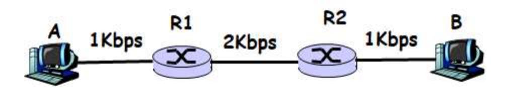
Consider the following network. Bandwidth of the link between A and R1 is $1$ Kbps. Bandwidth of the link between R1 and R2 is $2$ Kbps. Bandwidth of the link between R2 and B is $1$ Kbps. Assume that an application at A sends 10 packets each of size 1000 bytes. Assuming that the transmission starts at time 0, compute how long it takes for the last packet to arrive at B. Ignore the propagation, processing and queueing delays.
Solution
Analysis:
The bottleneck is the link with the minimum bandwidth. Here, both A→R1 and R2→B have 1 Kbps, while R1→R2 has 2 Kbps. So the bottleneck is 1 Kbps.
Packet Details:
- Packet size: 1000 bytes = 8,000 bits
- Number of packets: 10
Transmission Times:
Link A→R1 (1 Kbps): $t_{trans,1} = \frac{8,000}{1,000} = 8 \text{ seconds per packet}$ All 10 packets: $10 \times 8 = 80$ seconds
Link R1→R2 (2 Kbps): $t_{trans,2} = \frac{8,000}{2,000} = 4 \text{ seconds per packet}$ All 10 packets: $10 \times 4 = 40$ seconds
Link R2→B (1 Kbps): $t_{trans,3} = \frac{8,000}{1,000} = 8 \text{ seconds per packet}$ All 10 packets: $10 \times 8 = 80$ seconds
Timeline for Last Packet:
- Last packet finishes transmission on Link 1 (A→R1): 80 seconds
- Last packet starts transmission on Link 2 (R1→R2): 80 seconds (Router can immediately transmit)
- Last packet finishes transmission on Link 2: $80 + 4 = 84$ seconds
- Last packet starts transmission on Link 3 (R2→B): 84 seconds
- Last packet finishes transmission on Link 3 (arrives at B): $84 + 8 = 92$ seconds
Answer: 92 seconds
Alternatively: Total transmission time = Time to transmit all packets through bottleneck (1 Kbps) + time through middle link + time through last bottleneck: $T = 80 + 0 + 0 + 12 = 80 + 12 = 92 \text{ seconds}$
or more directly: $80 + 4 + 8 = 92$ seconds (time through each link in sequence for the batch)