02 - Link Layer-Physical Layer
Problem 1: Short Answer Questions
-
(a) What’s encapsulation as it applies to protocols. Briefly explain.
Solution
In short: Encapsulation is the process of wrapping data from a higher layer with header and trailer information from a lower layer. This allows each layer to add its own control information while preserving the original data, creating a nested structure of protocols.
Elaboration:
In a layered network model, encapsulation means that each protocol layer adds its own header (and sometimes trailer/footer) information to the data it receives from the layer above.
Example: When sending an email:
- Application Layer (SMTP) adds mail headers (To, From, Subject)
- Transport Layer (TCP) adds TCP header (ports, sequence numbers)
- Network Layer (IP) adds IP header (source/destination IP addresses)
- Link Layer (Ethernet) adds Ethernet header (MAC addresses) and trailer (CRC)
The original email data is completely wrapped by successive headers, allowing each layer to handle its responsibilities independently. At the receiving end, each layer unwraps the appropriate header to extract the data meant for the next layer up.
-
(b) Briefly explain the “framing” problem in the link layer and how PPP solves it.
Solution
In short: The framing problem is determining where one frame ends and the next begins in a continuous bit stream. PPP solves this by using a flag byte (0x7E) as a frame delimiter, and byte stuffing to ensure flag bytes in the payload don’t create false frame boundaries.
Elaboration:
The Framing Problem:
At the link layer, data is sent as a continuous stream of bits. The receiver needs to know where one frame ends and the next one begins—this is the framing problem. If you just send frames back-to-back, the receiver can’t determine the frame boundaries.
PPP’s Solution:
- Flag byte (0x7E) - Marks the beginning and end of frames
- Byte stuffing - If a 0x7E appears in the payload, it’s escaped by inserting 0x7D before it, and the byte is modified
- Escape character (0x7D) - Indicates the next byte should be interpreted differently
Example: If payload contains 0x7E, it’s transmitted as 0x7D 0x5E instead, preventing false frame boundaries.
Receiver recognizes frame boundaries by the flag bytes and de-stuffs escaped sequences to recover original data.
-
(c) In an Ethernet, why does doubling the bit rate (if everything else remains the same) require halving the maximum cable length?
Solution
In short: CSMA/CD collision detection requires that a station detect collisions before finishing transmission. Doubling the bit rate halves transmission time, so the cable must be shorter to allow collision signals to return before transmission completes.
Elaboration:
The CSMA/CD Constraint:
For CSMA/CD to work correctly, a sending station must detect a collision within the time it takes to send the minimum frame size. This constraint is:
$\text{Max cable length} = \frac{\text{Signal speed} \times \text{Minimum frame transmission time}}{2}$
The factor of 2 accounts for the signal traveling to the collision point and back.
When bit rate doubles:
- Transmission time for a fixed frame size halves: $t_{trans} = \frac{L}{R}$ decreases by half
- To maintain collision detection capability, maximum cable length must also halve
- Otherwise, collision signals wouldn’t reach the sender before transmission finishes
Example: If you double from 10 Mbps to 20 Mbps, maximum cable length goes from 2.5 km to 1.25 km.
-
(d) In a token ring, a station must wait for the token to come around to it before sending. Why is it not possible for the station to sense the ring and then start transmitting if there is no traffic?
Solution
In short: The ring is a shared medium, and sensing only tells you the current state—not whether another station will start transmitting. Without the token, you can’t guarantee exclusive access, leading to collisions.
Elaboration:
Why Token-based Access is Necessary:
In a token ring, the token provides guaranteed, exclusive access to the ring. Here’s why you can’t just sense the ring:
- Race condition - Multiple stations might simultaneously sense an idle ring and start transmitting, causing collisions
- Propagation delay - By the time you verify the ring is empty, another station at a different point in the ring might have already started transmitting
- Fairness - Sensing-based access (like CSMA) is unfair—faster stations get more access
- Distributed control loss - Without the token, there’s no way to ensure deterministic, fair, collision-free access
Token Advantage:
The token provides deterministic access—each station knows exactly when its turn comes, ensuring collisions never occur and guaranteeing fair bandwidth allocation.
-
(e) Smarty Smart thinks that having a minimum frame size is wasteful for Ethernet. He proposes that the minimum frame size be reduced to 19 bytes, 14 bytes for the header, 4 bytes for the CRC, and 1 byte for the payload. Explain why this may not be a good idea.
Solution
In short: Ethernet requires a minimum frame size to ensure CSMA/CD collision detection works correctly. With only 1 byte of payload, a frame would transmit in microseconds—too fast for collision signals to return, making collision detection unreliable.
Elaboration:
The CSMA/CD Requirement:
Ethernet uses CSMA/CD, which requires a station to detect collisions before finishing transmission. The minimum frame size (64 bytes in standard Ethernet) is specifically set to ensure this works:
$\text{Minimum frame time} \geq 2 \times \text{Maximum propagation delay}$
This ensures collision signals can travel from the far end of the cable and back before transmission finishes.
Why 19 bytes is problematic:
- A 19-byte frame transmits very quickly (microseconds on modern Ethernet)
- Collision detection signals take tens of microseconds to propagate
- The frame could finish transmitting before a collision signal returns
- Result: Collisions go undetected, corrupting the network
Padding Solution:
Ethernet solves this by requiring minimum 46 bytes of payload (padded if necessary), giving total minimum 64 bytes—not wasted, but essential for correct operation.
-
(f) In a broadcast channel, the link bandwidth is wasted due to multiple hosts trying to send at once and canceling each other’s communication. A simple model of this problem is that time is divided into discrete slots. If a network has n hosts, and the probability of any single host trying to use a slot is p, what fraction of slots are wasted due to collisions?
Solution
In short: A slot is wasted if either zero hosts or more than one host transmits. The probability of successful transmission (exactly one host transmitting) is $np(1-p)^{n-1}$, so the fraction of wasted slots is $1 - np(1-p)^{n-1}$.
Elaboration:
Slot Outcomes:
In each slot, one of three things happens:
- No transmission - Slot wasted (slot is empty)
- Exactly one transmission - Successful, slot used productively
- Multiple transmissions - Collision, slot wasted (data corrupted)
Probability Calculation:
For a single host: $P(\text{transmits}) = p$, $P(\text{doesn’t transmit}) = 1-p$
Probability of exactly one host transmitting: $P(\text{success}) = n \cdot p \cdot (1-p)^{n-1}$
This is the binomial probability: choose which of n hosts transmits, that host transmits (probability p), and the other n-1 don’t (probability $(1-p)^{n-1}$).
Fraction of wasted slots: $P(\text{wasted}) = 1 - np(1-p)^{n-1}$
Example: With n=2 hosts and p=0.5:
- $P(\text{success}) = 2 \cdot 0.5 \cdot 0.5 = 0.5$ (50% productive)
- $P(\text{wasted}) = 0.5$ (50% wasted)
-
(g) Explain the following terms: MTU, byte stuffing, bit stuffing
Solution
In short: MTU is the maximum transmission unit (largest frame size allowed). Byte stuffing inserts extra bytes to escape special delimiter bytes in the payload. Bit stuffing inserts extra 0 bits after sequences of consecutive 1 bits.
Elaboration:
MTU (Maximum Transmission Unit):
The largest frame that can be transmitted on a link layer protocol. If a higher layer needs to send more data, it must be fragmented into multiple frames.
- Ethernet MTU: 1500 bytes (payload)
- PPP MTU: 1500 bytes typically
- Jumbo frames: 9000+ bytes (non-standard)
Byte Stuffing:
A framing technique that escapes special delimiter bytes that appear in the payload.
- Flag byte (e.g., 0x7E in PPP) marks frame boundaries
- If 0x7E appears in payload, insert escape byte (0x7D) before it and modify the byte
- Example: Payload contains 0x7E → transmitted as 0x7D 0x5E
- At receiver: 0x7D 0x5E → restored to 0x7E
Bit Stuffing:
A framing technique that inserts extra bits to prevent certain bit patterns from appearing in the data.
- Pattern to avoid: Multiple consecutive 1 bits (to prevent confusion with frame delimiters)
- Solution: After every 5 consecutive 1 bits, insert a 0 bit
- Example: 1111111 → 1111101 (extra 0 inserted)
- At receiver: Removes the stuffed 0 bits to recover original data
- Used by: HDLC, some Ethernet implementations
-
(h) Consider 4 hosts, A, B, C and D attached together using an Ethernet hub into a star topology. Assume that A is sending some data to B. Is it possible for C to send some data to D at the same time? Justify your answer.
Solution
In short: No, it’s not possible. A hub broadcasts all frames to all ports, creating a shared medium. When A transmits, the hub forwards A’s signal to all other ports, making C’s transmission collide with A’s.
Elaboration:
How a Hub Works:
- A hub is a physical layer (Layer 1) device
- It simply repeats all signals to all other ports
- All hosts connected to a hub share a single collision domain
Why C and D can’t transmit simultaneously:
When A sends to B:
- A’s frames are sent to the hub
- Hub forwards A’s frames to all ports (including C and D)
- If C tries to transmit, C’s signal collides with the forwarded A signal
- CSMA/CD detects the collision and both A and C back off
- Neither transmission succeeds
Result: Only one host can transmit at a time in a hub-based network. The shared medium forces serialization of transmissions.
Contrast with Bridge/Switch:
A bridge or switch (Layer 2 devices) maintains separate collision domains per port, allowing simultaneous transmissions on different ports. This would allow A→B and C→D simultaneously.
-
(i) What’s the “type” or “protocolNo” field in a Link Layer (LL) header used for? Do all LLs have to have a “type” field in their headers? If a protocol does NOT have this field, what is the implication?
Solution
In short: The type field identifies which network layer protocol the frame contains (IP, IPX, AppleTalk, etc.). This allows the link layer to demultiplex frames to the correct network layer handler. Not all link layers have this field, but without it, only one protocol per link is supported.
Elaboration:
Purpose of the Type Field:
The type (or EtherType in Ethernet) field in the link layer header indicates which network layer protocol the frame’s payload is intended for.
Common Type Values (Ethernet):
- 0x0800 - IP (IPv4)
- 0x0806 - ARP (Address Resolution Protocol)
- 0x86DD - IPv6
- 0x809B - AppleTalk
Without Type Field (Implications):
- Single protocol only - The link layer can only support one network layer protocol
- No demultiplexing - The receiver doesn’t know which protocol handler should process the frame
- Limited flexibility - Can’t have multiple protocols on the same link simultaneously
- Design constraint - Simplified protocols (like early point-to-point links) often omit this
Example:
- Ethernet has type field → supports IP, AppleTalk, IPX on same link
- PPP has protocol field → supports IP, IPX, etc. on same link
- Older point-to-point links often had no type field → only IP supported
-
(j) Consider a link layer that does NOT add error detection/correction bits to the end of its frames? What are the implications of this design?
Solution
In short: Without error detection, corrupted frames pass undetected to higher layers. This forces upper layer protocols to detect and handle all errors, increases overhead, and reduces reliability. It only works if the physical medium is extremely reliable.
Elaboration:
Implications of No Error Detection:
-
Undetected corruption
- Frames corrupted by noise pass through without detection
- Corrupted data delivered to the application layer
- Application receives incorrect information without knowing
-
Error handling burden on higher layers
- Transport layer (TCP) must handle all error detection
- TCP adds checksums, sequence numbers, acknowledgments
- Increases overhead at every protocol layer
-
Reduced efficiency
- No early detection at link layer means wasted transmission time
- Corrupted frames occupy bandwidth unnecessarily
- TCP timeout-based retransmission is slow compared to immediate link-layer detection
-
Reliability degradation
- Gaps in error detection between layers
- Some applications (UDP) might not detect errors at all
When this might be acceptable:
- Very reliable physical media - Fiber optic, wired LANs with low error rates
- Real-time constraints - Where detection overhead is unacceptable (rare)
- Point-to-point links - Where physical quality is guaranteed
Modern approach: Always include error detection (CRC) at link layer for efficiency and reliability.
-
-
(k) Why is it important for protocols configured on top Ethernet to have a length in their header indicating how long the message is?
Solution
In short: Ethernet allows frames to be padded to the 64-byte minimum, so the receiving protocol needs a length field to know where the actual payload ends and where padding begins. Without it, the receiver can’t distinguish data from padding.
Elaboration:
Ethernet Frame Structure:
- Minimum frame size: 64 bytes (14 byte header + 4 byte trailer + at least 46 bytes payload)
- Maximum frame size: 1518 bytes
- If payload is less than 46 bytes, Ethernet pads with zeros
The Problem:
Suppose you send a 10-byte IP packet:
- Ethernet pads it with 36 bytes of zeros to reach 46 bytes minimum payload
- Total frame: 10 bytes IP + 36 bytes padding
- At receiver: Just sees 46 bytes of data
How does the receiver know the true message length?
Without a length field in the IP header, the receiver can’t tell where real data ends and padding begins.
IP Header Solution:
IP header includes a Total Length field indicating the actual IP datagram size (10 bytes in our example). This allows the IP layer to:
- Know to extract only 10 bytes of payload
- Ignore the 36 padding bytes
- Not pass padding to the application layer
General Rule:
Any protocol layered on top of Ethernet (or any link layer with padding) needs a length field or another demarcation method to handle padding correctly.
-
(l) What’s a MAC address. What is it used for?
Solution
In short: A MAC (Media Access Control) address is a 48-bit (6-byte) hardware address identifying a network interface on the local link. It’s used to deliver frames to the correct physical port on an Ethernet switch or to the correct neighbor on a shared medium.
Elaboration:
MAC Address Format:
- Length: 48 bits (6 bytes)
- Format: Written as hexadecimal:
00:1A:2B:3C:4D:5E - Uniqueness: First 24 bits (OUI) identify manufacturer; last 24 bits are unique per vendor
Example:
FF:FF:FF:FF:FF:FF- Broadcast address (all interfaces)00:00:5E:00:01:00- Multicast address08:00:27:00:00:00- Unicast address
What MAC Addresses are Used For:
- Link-layer delivery - Identifying the physical interface on the local network
- Ethernet switching - Switches use MAC addresses to forward frames to correct ports
- ARP (Address Resolution Protocol) - Maps IP addresses to MAC addresses
- Local network communication - Delivering frames between neighbors
Scope: MAC addresses are meaningful only on the local network segment (same LAN). They change as packets traverse different links, while IP addresses remain constant end-to-end.
Frame Structure Example:
Destination MAC | Source MAC | Type | Payload | CRC 48 bits | 48 bits | 16 | | 32 -
(m) Briefly describe how Ethernet’s Carrier Sense Multiple Access/Collision Detection (CSMA/CD) work? What’s the advantage of CSMA/CD over CSMA?
Solution
In short: CSMA/CD allows stations to transmit when the medium is idle, and immediately detect collisions by sensing if another signal is present. When a collision is detected, stations back off and retry. CSMA/CD is faster than CSMA because it detects collisions immediately rather than waiting for timeouts.
Elaboration:
How CSMA/CD Works:
-
Carrier Sense - Before transmitting, listen to the medium
- If idle → start transmitting
- If busy → wait until it becomes idle
-
Multiple Access - All stations have equal access to the shared medium
- No token or priority system
- Anyone can transmit when the medium is idle
-
Collision Detection - While transmitting, listen for collisions
- If you detect another signal while sending → collision!
- Immediately stop transmission
-
Backoff - After detecting collision:
- Send a “jam signal” to alert other stations
- Wait a random backoff time
- Retry transmission
CSMA vs CSMA/CD:
CSMA (without CD):
- Transmit when medium is idle
- No collision detection
- Wait for entire frame transmission + timeout to realize collision
- High latency for error recovery
CSMA/CD (with Collision Detection):
- Transmit when medium is idle
- Detect collisions immediately
- Stop transmission early, saving bandwidth
- Backoff and retry much faster
- Advantages:
- Faster recovery from collisions
- Better link utilization (don’t waste time sending entire corrupted frames)
- More efficient on longer cables (can detect collisions quickly)
Limitation of CSMA/CD: Requires collision detection capability (voltage sensing), which is difficult at very high speeds.
-
-
(n) Briefly describe how channel partitioning MAC algorithms work. Also describe their advantages and disadvantages.
Solution
In short: Channel partitioning divides the medium into exclusive sub-channels and allocates one to each station or dynamically to active stations. Eliminates collisions but wastes bandwidth when stations are idle. Examples: FDMA, TDMA, CDMA.
Elaboration:
How Channel Partitioning Works:
The shared medium is divided into separate channels or time slots, each allocated to a specific station or set of stations.
Three Main Approaches:
-
Frequency Division Multiple Access (FDMA)
- Divide bandwidth into frequency bands
- Each station gets exclusive frequency band
- Example: Radio stations (88-108 MHz for FM)
-
Time Division Multiple Access (TDMA)
- Divide time into slots
- Each station gets exclusive time slots
- Example: GSM cellular (each call gets time slots)
-
Code Division Multiple Access (CDMA)
- Each station gets unique code/key
- All stations can transmit simultaneously with their code
- Example: CDMA cellular networks
Advantages of Channel Partitioning:
- No collisions - Guaranteed exclusive access, deterministic behavior
- Fair allocation - All stations get equal access opportunity
- Predictable performance - Latency and throughput are deterministic
- Works for continuous traffic - Good for voice, streaming
Disadvantages of Channel Partitioning:
- Bandwidth waste - Idle stations still reserve their channel/slot
- Overhead - Complexity of managing and synchronizing divisions
- Inflexible - Can’t dynamically allocate more bandwidth to heavy users
- Setup required - Need central authority to manage partitions
- Poor for bursty traffic - Allocated slot is wasted when station has no data
When to use: Predictable traffic patterns, voice calls, real-time applications. Not ideal for Internet data (which is bursty).
-
-
(o) Ethernet has two encapsulation formats: The traditional Ethernet encapsulation with 14 bytes of header and 802.3 encapsulation. How long can a packet in 802.3 encapsulation be? Justify your answer.
Solution
In short: In 802.3 encapsulation, a packet can be up to 1500 bytes (this is called the MTU). The 802.3 header includes a length field with 16 bits, allowing values 0-65535, but the practical limit is 1500 bytes due to hardware constraints and compatibility.
Elaboration:
Ethernet Frame Structure (802.3):
Preamble | SFD | Dest MAC | Src MAC | Length | Payload | CRC
7 bytes  | 1   | 6       | 6      | 2      | 0-1500  | 4
Length Field:
- Size: 16 bits
- Range: 0 to 65,535 bytes
- But: Limited to 1500 bytes maximum
Why 1500 Bytes Maximum:
- 802.3 specification - Defines MTU as 1500 bytes for standard Ethernet
-
Minimum frame size - Total frame is 64 bytes minimum (to accommodate CSMA/CD)
- If payload is less than 46 bytes → padded with zeros
- 14 (header) + 4 (CRC) + 46 (minimum payload) = 64 bytes
- Hardware limitations - Most hardware buffers are designed for 1500-byte payloads
- Interoperability - Devices expect this MTU value
Maximum Frame Calculation:
- Preamble: 7 bytes
- SFD: 1 byte
- Destination MAC: 6 bytes
- Source MAC: 6 bytes
- Length field: 2 bytes
- Payload: 1500 bytes
- CRC: 4 bytes
- Total: 1526 bytes
Jumbo Frames: Non-standard extension allowing up to 9000 bytes, but not interoperable with all equipment.
-
(p) Briefly explain the difference between serial and parallel communication. Which is preferred in long distance communication?
Solution
In short: Serial communication sends bits one at a time sequentially over a single line; parallel sends multiple bits simultaneously over multiple lines. Serial is preferred for long distances due to lower cost and better signal integrity.
Elaboration:
Parallel Communication:
- Multiple bits transmitted simultaneously over multiple wires
- Example: 8 bits sent on 8 parallel wires in one time unit
- High throughput - Can send many bits per time unit
- Short distances - Works well (few meters)
- Examples: PCI bus, printer parallel port, internal computer busses
Serial Communication:
- One bit transmitted at a time over a single wire (plus ground)
- Example: 8 bits sent sequentially, one bit per time unit
- Lower throughput - Slower bit rate per wire
- Lower bandwidth required - Single line instead of many
- Examples: USB, Ethernet, RS-232, UART
Why Parallel is Problematic for Long Distances:
- Multiple wires cost - More expensive cable with many conductors
- Skew/timing issues - Different wires have different propagation delays
- Bits arrive at slightly different times
- Can cause data corruption
- Crosstalk - Signal interference between adjacent wires
- Impedance matching - Difficult to maintain on long parallel cables
- Noise susceptibility - More lines = more potential noise pickup
Why Serial is Preferred for Long Distance:
- Single wire - Cheap, simple cable
- Timing - No skew issues (only one bit at a time)
- Noise resistant - Single wire easier to shield
- Long reach - Works over kilometers (Ethernet, optical fiber)
- Standards - Well-established for long-distance (RS-485, USB, Ethernet)
Modern trend: Even local interconnects moving toward serial (high-speed serial links in PCIe, USB 3.0) for reliability and scalability.
-
(q) Briefly explain the difference between synchronous and asynchronous communication. Which is preferred in long distance communication and why?
Solution
In short: Synchronous communication uses a shared clock to time bit transmission, while asynchronous relies on start/stop bits to synchronize. Asynchronous is preferred for long distance because clock synchronization is difficult and unnecessary for low-speed communication.
Elaboration:
Synchronous Communication:
- Shared clock signal between sender and receiver
- Bits transmitted and sampled at precise clock times
- No framing bits needed - Clock tells receiver exactly when to sample
- High efficiency - Every bit carries data
- Examples: SPI, I2C, networked systems with clock recovery
Advantages:
- No overhead for start/stop bits
- Higher efficiency for continuous data
- Good for high-speed communication
Disadvantages:
- Requires clock signal separate from data (or embedded clock recovery)
- Both clocks must stay synchronized
- Difficult over long distances with clock drift
Asynchronous Communication:
- No shared clock - Each side has its own clock
- Start bit signals beginning of character
- Stop bit(s) signals end of character
- Receiver uses start bit to synchronize to transmitter
- Examples: RS-232, TTY, terminal connections
Advantages:
- No clock signal needed
- Works with slightly mismatched clocks (within tolerance)
- Simple to implement
Disadvantages:
- Start/stop bits are overhead (~2 bits per 8-bit character = 20% overhead)
- Lower efficiency
- Limited speed
Long Distance Preference: Asynchronous
Why asynchronous wins for long distance:
-
Clock distribution problem - Synchronous requires:
- Separate clock line(s)
- Clock recovery circuitry at each end
- Phase synchronization over long cables with propagation delays
-
Clock drift - Over long distances:
- Clocks can drift apart (temperature, manufacturing tolerance)
- Synchronous loses sync, requiring resynchronization
-
Simplicity - Asynchronous needs:
- Single data line (plus ground)
- Simple start/stop bit detection
- Tolerant of moderate speed variations
-
Modern alternative: High-speed synchronous uses clock recovery from data patterns, common in Ethernet and fiber optics.
Example: Old modems used asynchronous (RS-232) for dial-up, which worked over phone lines. Modern Ethernet is technically synchronous but recovers clock from the signal itself.
-
(r) Give a list of the 3 types of cables used in communication networks. Which cables do high speed Ethernet use?
Solution
In short: The three main cable types are twisted pair (copper), coaxial (copper), and fiber optic. Modern high-speed Ethernet predominantly uses twisted pair (Cat 5e/6/6A) and fiber optic for long distances or very high speeds.
Elaboration:
Three Main Cable Types:
1. Twisted Pair (Copper)
- Construction: Pairs of insulated copper wires twisted together
- Categories:
- Cat 5e: 1 Gbps (100 meters)
- Cat 6: 10 Gbps (55 meters)
- Cat 6A: 10 Gbps (100 meters)
- Cat 7: 10 Gbps+ (100 meters)
- Advantages: Cheap, easy to install, good for short-to-medium distance
- Disadvantages: Attenuation increases with distance; susceptible to interference
- Used for: Ethernet (most common), telephone lines
2. Coaxial Cable
- Construction: Inner conductor surrounded by insulator, then shield (mesh), then outer jacket
- Examples: RG-58, RG-59
- Advantages: Better shielding than twisted pair; longer distance capability
- Disadvantages: Thicker, harder to install, more expensive
- Used for: Old Ethernet (10BASE-2, 10BASE-5), cable TV, sometimes analog video
- Note: Mostly obsolete in networking
3. Fiber Optic
- Construction: Hair-thin glass/plastic core with protective cladding and jacket
- Types:
- Single-mode: Long distance (10+ km), more expensive
- Multi-mode: Medium distance (500-2000 m), cheaper
- Advantages: Highest speed, longest distance, immune to electromagnetic interference
- Disadvantages: Most expensive, requires special equipment, fragile
- Used for: Long-distance backbone links, high-speed links, data centers
High-Speed Ethernet Cable Usage:
1 Gbps (Gigabit Ethernet):
- Twisted pair: Cat 5e minimum (most common)
- Fiber optic: Multi-mode or single-mode
10 Gbps (10 Gigabit Ethernet):
- Twisted pair: Cat 6A or Cat 7 (limited to 55m without special techniques)
- Fiber optic: Single-mode preferred (longer distances)
40+ Gbps (High-speed):
- Primarily fiber optic - Twisted pair becomes impractical
- Single-mode for backbone, multi-mode for data centers
Practical Modern Deployment:
- Local offices: Cat 6/6A twisted pair
- Data centers: Mix of twisted pair and multi-mode fiber
- Backbone/long-distance: Single-mode fiber optic
-
(s) Briefly explain the difference between modulation and encoding.
Solution
In short: Encoding converts digital data (1s and 0s) into signals suitable for transmission (voltage levels, light pulses). Modulation modifies a carrier signal to encode information and adapt it to the transmission medium characteristics.
Elaboration:
Encoding (Digital-to-Signal Conversion):
Encoding is the process of representing digital data (1s and 0s) as physical signals.
Common Encoding Schemes:
-
NRZ (Non-Return-to-Zero)
- 1 = high voltage (+V)
- 0 = low voltage (-V)
- Simple but lacks clock recovery mechanism
-
Manchester Encoding
- 1 = high→low transition
- 0 = low→high transition
- Advantages: Self-clocking, helps with synchronization
-
4B/5B Encoding
- Groups 4 data bits into 5 signal bits
- Better DC balance; used in Fast Ethernet
Purpose: Convert digital data to electrical/optical signals that can be transmitted on the medium.
Modulation (Analog Signal Modification):
Modulation is the process of modifying a carrier signal (high-frequency signal) to encode information and adapt it to the transmission medium.
Types of Modulation:
-
Amplitude Modulation (AM)
- Vary signal strength/amplitude to represent data
- Used in: AM radio, older modems
-
Frequency Modulation (FM)
- Vary signal frequency to represent data
- Used in: FM radio, FSK (Frequency Shift Keying) modems
-
Phase Modulation (PM)
- Vary signal phase to represent data
- Used in: PSK (Phase Shift Keying), high-speed modems
-
QAM (Quadrature Amplitude Modulation)
- Combines amplitude and phase variations
- Used in: Cable modems, DSL, 4G/5G
Key Differences:
Aspect Encoding Modulation Input Digital bits (1/0) Digital bits Output Physical signal Carrier signal + data Domain Baseband (low frequency) RF/analog (high frequency) Purpose Signal representation Frequency adaptation Example Manchester encoding AM, FM, QAM When Each is Used:
- Encoding: Always used to convert digital to physical
- Modulation: Used when transmitting over:
- Long distances requiring high-frequency carriers
- Wireless (RF) channels
- Analog infrastructure (phone lines)
Example Path:
Digital data → Encoding → Digital signal
            ↓
Digital signal → Modulation → Analog carrier signal (for wireless/long-distance)
Modern Perspective: Optical Ethernet uses encoding (on/off of light) but not modulation (no carrier wave), directly encoding bits as light pulses.
-
Problem 2: CRC and Parity-Based Error Detection
Suppose you want to transmit the following 10-bit message “0100101100”.
-
(a) Suppose you want to protect the message from errors using the CRC polynomial $x^4 + x^3 + x$ . Use polynomial long division to determine the message that would be transmitted.
Solution
-
(b) Suppose you want to protect the message from errors using two-dimensional odd parity. Assume that the message is divided into 5-bit chunks for parity computation purposes. Determine the message that would be transmitted.
Solution
Problem 3: Checksum and One-Dimensional Parity
Suppose you want to transmit the following 12-bit message “110010011111”.
-
(a) Suppose you want to protect the message from errors using a checksum by dividing the message into 4-bit chunks and performing 1s complement addition. Show the EDC bits that will be transmitted. Show your work.
Solution
-
(b) Suppose you want to protect the message from errors using one-dimensional even parity. Assume that the message is divided into 4-bit chunks for parity computation purposes. Determine the message that would be transmitted. Show the parity bits for each chunk.
Solution
Problem 4: CRC Polynomial Computation and Error Detection
Suppose you want to transmit the message 11011010 and protect it from errors using the CRC polynomial $x^3 + x^2 + 1$. Use polynomial long division to determine the message that would be transmitted. Assume no bit errors occur during transmission. How does the receiver know that the frame was received without any errors?
Solution
Problem 5: CRC Error Detection Mechanism
Suppose you want to transmit the message 11001001 and protect it from errors using the CRC polynomial $x^3 + 1$. Use polynomial long division to determine the message that would be transmitted. Assume no bit errors occur during transmission. How does the receiver know that the frame was received without any errors?
Solution
Problem 6: CRC Bit Error Detection and Checksum Comparison
Suppose you want to transmit the message 11001001 and protect it from errors using the CRC polynomial $x^3 + 1$
-
(a) Use polynomial long division to determine the message that would be transmitted.
Solution
-
(b) Suppose the leftmost bit of the message is inverted due to noise on the transmission link. What’s the receiver’s CRC calculation? How does the receiver know that an error has occurred?
Solution
-
(c) Describe the advantages and disadvantages of using checksums instead of CRC for error detection and correction at the link layer.
Solution
Problem 7: Byte-Counting, Byte-Stuffing, and Bit-Stuffing Framing
Suppose you want to transmit the following 4-byte message “0xfb 0x7e 0x7d 0xff” with 0xfb being transmitted first.
-
(a) Assume that the link layer uses byte-counting for framing and has a one-byte length field in the header. Show the bytes transmitted on the wire as hexadecimal numbers.
Solution
Solution:
Message:
0xfb 0x7e 0x7d 0xff(4 bytes)Byte-counting framing:
- Header contains length field (1 byte) indicating payload size
- Length: 4 bytes
- Header:
0x04
Bytes transmitted:
0x04 0xfb 0x7e 0x7d 0xff(Length field followed by 4 payload bytes)
-
(b) Assume that the link layer uses byte-stuffing, using 0x7e as the frame delimiter and 0x7d as the escape character. Show the bytes transmitted on the wire.
Solution
Solution:
Frame delimiters: 0x7e marks frame boundaries Escape character: 0x7d escapes special bytes
Message:
0xfb 0x7e 0x7d 0xffByte-stuffing process:
- Start frame delimiter:
0x7e - Process each byte:
0xfb: No special meaning → transmit as0xfb0x7e: This is frame delimiter! → escape:0x7d 0x5e(0x7d followed by modified 0x7e)0x7d: This is escape character! → escape:0x7d 0x5d(0x7d followed by modified 0x7d)0xff: No special meaning → transmit as0xff
- End frame delimiter:
0x7e
Bytes transmitted:
0x7e 0xfb 0x7d 0x5e 0x7d 0x5d 0xff 0x7e(Start flag + payload with stuffing + end flag)
- Start frame delimiter:
-
(c) Assume that the link layer uses bit-stuffing, stuffing an extra 0 bit after 5 consecutive 1 bits. Show the bits transmitted on the wire clearly marking the stuffed bits. Recall that a link that uses bitstuffing still uses 0x7e as the frame delimiter.
Solution
Solution:
Message:
0xfb 0x7e 0x7d 0xffConvert to binary:
0xfb= 1111 10110x7e= 0111 11100x7d= 0111 11010xff= 1111 1111
Frame structure:
- Start delimiter:
0x7e= 0111 1110 - Payload:
0xfb 0x7e 0x7d 0xff - End delimiter:
0x7e= 0111 1110
Bit-stuffing process (insert 0 after every 5 consecutive 1s):
Start delimiter: 0111 1110
             → 0111 1110 (no 5 consecutive 1s)

0xfb = 1111 1011
    → 1111 1[0]011 (5 consecutive 1s at position 0-4, insert 0 after bit 5)
    → 1111 10011

0x7e = 0111 1110
    → 0111 1110 (has 4 consecutive 1s at end, not 5)

0x7d = 0111 1101
    → 0111 1101

0xff = 1111 1111
    → 1111 1[0]111 (insert 0 after first 5 ones)
    → 1111 10111 (now checking: 10111, not 5 consecutive)
    → ends with 111, only 3 consecutive
    → 1111 10111

End delimiter: 0111 1110
Complete bit sequence transmitted:
0111 1110  |  1111 10011  |  0111 1110  |  0111 1101  |  1111 10111  |  0111 1110
 (start)   |    (0xfb)    |    (0x7e)   |    (0x7d)   |    (0xff)     |   (end)
Where stuffed bits are: After each group of 5 consecutive 1s, a [0] is inserted in brackets above.
Total bits transmitted: (7 bytes * 8 bits) + (stuffed 0s) = approximately 64 bits depending on stuffing
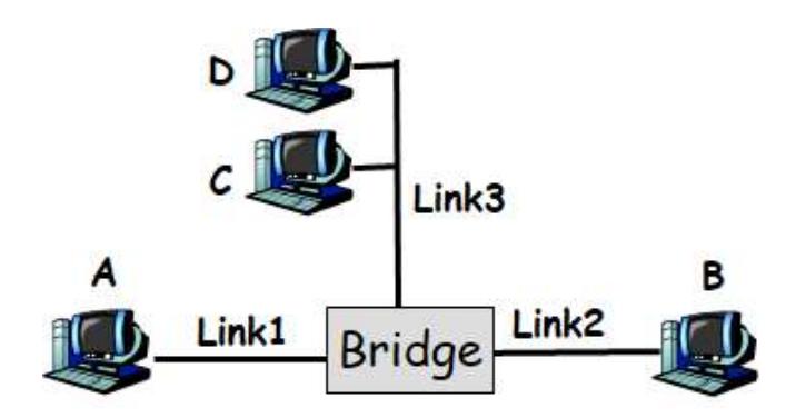
Problem 8: Hub vs Bridge Network Interconnection
Consider a broadcast link L1 containing hosts A and B. Further consider another link L2 containing nodes C and D. Answer the following questions:
-
(a) Assume L1 and L2 are attached together with a hub. Does host A now need to compete with hosts C and D to gain control of the link? Why or why not? What’s your answer if L1 and L2 are attached by a bridge?
Solution
In short: With a hub, all hosts (A, B, C, D) share a single collision domain, so A must compete with C and D using CSMA/CD. With a bridge, L1 and L2 are separate collision domains, allowing simultaneous transmissions on different links without contention.
Elaboration:
With a HUB:
- YES, A must compete with C and D for link access
- A hub is a Layer 1 (Physical) device that simply repeats all signals to all ports
- All hosts (A, B, C, D) are in a single shared collision domain
- CSMA/CD applies to the entire network - only one station can transmit at a time
- A must use CSMA/CD to sense the channel and avoid collisions with C and D
With a BRIDGE:
- NO, A does NOT need to compete with C and D
- A bridge is a Layer 2 (Link) device that maintains separate collision domains
- L1 (containing A, B) is one collision domain
- L2 (containing C, D) is another collision domain
- A can transmit on L1 while C or D transmits on L2 simultaneously
- The bridge forwards frames between links when needed
-
(b) Assume L1 and L2 are attached together with a bridge. Assume A sends a packet to B immediately after the links are attached. Does the bridge forward the packet to link L2? Why or why not?
Solution
In short: When A sends to B initially, the bridge doesn’t yet know B’s location. Following the conservative forwarding rule for unknown destinations, the bridge floods the packet to all ports except the incoming port, including L2.
Elaboration:
On first packet: YES, it will forward initially (unknown destination → flood) After learning: NO, the bridge does NOT forward to L2
Reason: Bridge Learning and Forwarding
- When A sends to B, the bridge examines the frame:
- Source MAC: A (on L1)
- Destination MAC: B
- B is also on L1
- The bridge has learned that A is reachable on L1
- The bridge does not know yet where B is located
- Following the conservative flooding rule: forward unknown destinations to all ports except the incoming port
- But more importantly: B is on L1, so the bridge should not forward to L2
- Actually, on first packet: the bridge hasn’t learned anything yet
- With unknown destination B: bridge floods to all ports (including L2)
- So actually YES, it will forward initially (unknown destination → flood)
- After learning that B is on L1: subsequent packets to B won’t be forwarded
- When A sends to B, the bridge examines the frame:
-
(c) Assume L1 and L2 are attached together with a bridge. Assume A sends a packet to B immediately after the links are attached. Further assume that B immediately replies back to A. Does the bridge forward the packet to link L2? Why or why not?
Solution
In short: After A’s initial packet, the bridge learns A is on L1. When B replies, the bridge learns B is also on L1. Since both source and destination are on L1, the bridge does not forward to L2, preventing unnecessary inter-link traffic.
Elaboration:
NO, the bridge does NOT forward to L2
Assuming the bridge has learned locations from part (b):
After A’s initial packet to B:
- Bridge learned: A is on L1
- Bridge may not yet know where B is (if B hasn’t sent anything)
When B replies to A:
- Frame: Src=B, Dst=A
- Source MAC B is on L1 → bridge learns: B is on L1
- Destination MAC A is on L1 → bridge has already learned A is on L1
- Bridge has entries for both A and B pointing to L1
- NO, the bridge does NOT forward to L2
- The bridge knows both A and B are on L1, so it doesn’t need to forward to L2
- Forwarding to L2 would be unnecessary and wasteful
Problem 9: Ethernet vs FDDI Network Selection
Some network applications are a better match for an Ethernet, some are a better match for an FDDI (token ring) network. Which network would be better match for a remote terminal application (e.g., Telnet) and which would be better for a file transfer application (e.g., FTP)? Give a general explanation for what it is about each of these applications that suggest that one type of network is better match than the other?
-
(a) Answer
Solution
In short: Telnet (interactive, bursty) benefits from FDDI’s deterministic access and fairness, eliminating collision delays. FTP (bulk, continuous) benefits from Ethernet’s simpler protocol and better frame utilization for large transfers.
Elaboration:
Remote Terminal (Telnet) → FDDI (Token Ring)
Why FDDI is better:
- Interactive traffic: Telnet is bursty with small, irregular packets (key presses)
- Latency-sensitive: User expects quick response (low latency)
- Token ring advantage: Deterministic access time
- Each station gets its turn at regular intervals
- Maximum latency is bounded and predictable
- No collision delays or CSMA/CD backoffs
- FDDI benefit: Fair bandwidth allocation
- Heavy users can’t starve light users
- Interactive traffic gets responsive service
- Collision overhead minimized: Token ring has no collisions
- Telnet doesn’t need large frames, so padding isn’t a big issue
File Transfer (FTP) → Ethernet (CSMA/CD)
Why Ethernet is better:
- Bulk data transfer: FTP sends large continuous streams of data
- Throughput-driven: FTP prioritizes total data transmitted per unit time
- Ethernet advantage: Better link utilization for continuous traffic
- No token circulation overhead
- Can transmit whenever ready (simpler protocol)
- Large frames amortize header overhead well
- Token ring disadvantage: Latency of waiting for token
- For long FTP transfers, token circulation overhead is significant
- Wasted time passing token around to stations with no data
- Collision handling: FTP can handle occasional collisions well
- Large file means many frames, so occasional retransmissions aren’t critical
- Relative to total data, collision overhead is minimal
- TCP handles retransmission anyway
Summary Comparison:
Metric Telnet (Interactive) FTP (Bulk) Traffic pattern Bursty, small Continuous, large Latency requirement Low Moderate Throughput requirement Low High Best network Token Ring (FDDI) Ethernet (CSMA/CD) Key reason Deterministic latency Link efficiency General Principle:
- Token Ring/FDDI: Best for interactive applications where latency predictability matters more than absolute throughput
- Ethernet/CSMA/CD: Best for bulk data applications where throughput matters more than latency, and applications can tolerate occasional delays from collisions
Problem 10: Ethernet Maximum Cable Length with CSMA/CD
Determine the maximum length of an Ethernet cable in kilometers with CSMA/CD for transmitting data at a rate of 500 Mbps with frame size of 10.000 bits. Assume that the signal speed in the cable is 2x10⁵ km/sec. Show your work. (Answer: 2 km)
Solution
In short: CSMA/CD requires collision detection before transmission ends. Maximum cable length equals (signal speed × transmission time) / 2. At 500 Mbps with 10,000-bit frames, transmission time is 20 microseconds, yielding maximum length of 2 km.
Elaboration:
CSMA/CD Requirement:
For CSMA/CD to work, a sending station must detect a collision before finishing transmission of its frame. This requires:
$\text{Propagation delay} \leq \frac{1}{2} \times \text{Transmission time}$
Or equivalently: $\text{Max cable length} = \frac{\text{Signal speed} \times \text{Transmission time}}{2}$
The factor of 2 accounts for the signal traveling to the collision point and back.
Step 1: Calculate transmission time
$t_{trans} = \frac{\text{Frame size}}{\text{Bit rate}} = \frac{10,000 \text{ bits}}{500 \times 10^6 \text{ bits/sec}} = \frac{10^4}{5 \times 10^8} = 2 \times 10^{-5} \text{ seconds}$
$t_{trans} = 20 \text{ microseconds}$
Step 2: Calculate maximum cable length
$L_{max} = \frac{s \times t_{trans}}{2}$
where $s$ = signal speed = $2 \times 10^5$ km/sec
$L_{max} = \frac{2 \times 10^5 \text{ km/sec} \times 2 \times 10^{-5} \text{ sec}}{2}$
$L_{max} = \frac{4 \times 10^0 \text{ km}}{2} = \frac{4 \text{ km}}{2} = 2 \text{ km}$
Answer: Maximum cable length = 2 km
Physical interpretation:
- A signal can travel 2 km in $2 \times 10^{-5}$ seconds
- If a collision occurs at the far end (2 km away), the signal needs to travel back (another 2 km), taking a total of $4 \times 10^{-5}$ seconds
- This is longer than the transmission time of $2 \times 10^{-5}$ seconds
- Therefore, the sender would finish transmitting before detecting the collision
- This means 2 km is the maximum safe cable length for CSMA/CD to function properly
Problem 11: Minimum Frame Size for CSMA/CD
A link layer protocol with CSMA/CD in the MAC layer is running at 1 Gbps over a 1km cable. The signal speed in the cable is 2x10⁵ km/sec. What should be the minimum frame size for the link layer? Show your work (Answer: 10.000 bits)
Solution
In short: For CSMA/CD to detect collisions, transmission time must be at least twice the propagation delay (10 microseconds). At 1 Gbps, this requires minimum frame size of 10,000 bits to maintain reliable collision detection.
Elaboration:
CSMA/CD Requirement:
For CSMA/CD to work properly, the transmission time must be at least twice the propagation delay:
$t_{trans} \geq 2 \times t_{prop}$
Or in terms of frame size:
$\text{Frame size} \geq 2 \times \text{Bit rate} \times t_{prop}$
Step 1: Calculate propagation delay
$t_{prop} = \frac{\text{Cable length}}{\text{Signal speed}} = \frac{1 \text{ km}}{2 \times 10^5 \text{ km/sec}} = \frac{1}{2 \times 10^5} = 5 \times 10^{-6} \text{ seconds}$
$t_{prop} = 5 \text{ microseconds}$
Step 2: Calculate minimum transmission time
For collision detection to work:
$t_{trans,min} = 2 \times t_{prop} = 2 \times 5 \times 10^{-6} = 10 \times 10^{-6} = 10^{-5} \text{ seconds}$
$t_{trans,min} = 10 \text{ microseconds}$
Step 3: Calculate minimum frame size
$\text{Frame size}{min} = \text{Bit rate} \times t{trans,min}$
$\text{Frame size}_{min} = 10^9 \text{ bits/sec} \times 10^{-5} \text{ sec} = 10^4 \text{ bits}$
$\text{Frame size}_{min} = 10,000 \text{ bits}$
Answer: Minimum frame size = 10,000 bits = 1,250 bytes
Physical interpretation:
- Propagation delay: 5 microseconds each way
- For collision detection: sender must still be transmitting when collision signal returns
- Return time: 2 × 5 = 10 microseconds
- At 1 Gbps, 10,000 bits takes exactly 10 microseconds to transmit
- Therefore, minimum frame size must be 10,000 bits
Note: This is the minimum theoretical size. Ethernet standard specifies 64 bytes (512 bits) minimum, then pads to 64 bytes, which is larger than 10,000 bits in total frame size.
Problem 12: Bridge Forwarding and MAC Learning
Consider the following LAN consisting of 3 links attached by a bridge. For each of the following cases, describe which links does the bridge forward the packet to and show the bridge forwarding table after the packet is sent.
-
(a) A sends a packet to B.
Solution
Forwarding Decision: Floods to network 2, 3 (destination B is unknown)
Bridge Forwarding Table After: | MAC Address | Port | |————-|——| | A | 1 |
-
(b) C sends a packet to B.
Solution
Forwarding Decision: Floods to network 1, 2 (destination B is unknown)
Bridge Forwarding Table After: | MAC Address | Port | |————-|——| | A | 1 | | C | 3 |
-
(c) A sends a packet to C.
Solution
Forwarding Decision: Forward to port 2 only (C is known on port 3, and A is sending from port 1, so forward only to port 2)
Bridge Forwarding Table After: | MAC Address | Port | |————-|——| | A | 1 | | C | 3 |
(No change - C was already known)
-
(d) B sends a packet to D.
Solution
Forwarding Decision: Floods to network 2, 3 (destination D is unknown)
Bridge Forwarding Table After: | MAC Address | Port | |————-|——| | A | 1 | | B | 2 | | C | 3 |
-
(e) C sends a packet to D.
Solution
Forwarding Decision: Floods to network 1, 2 (destination D is unknown)
Bridge Forwarding Table After: | MAC Address | Port | |————-|——| | A | 1 | | B | 2 | | C | 3 |
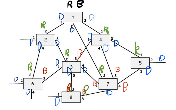
Problem 13: Perlman’s Spanning Tree Algorithm
Consider the following LAN consisting of 8 bridges numbered 1-8 with the given connections. Each interface of each bridge is also labeled starting with 1. Run Perlman’s Spanning Tree Algorithm and for each interface of each bridge write down whether the interface is a “Root port (R)”, a “Designated port (D)” or “Blocking Port (B)” in the tables given below. Finally, show the final spanning tree.
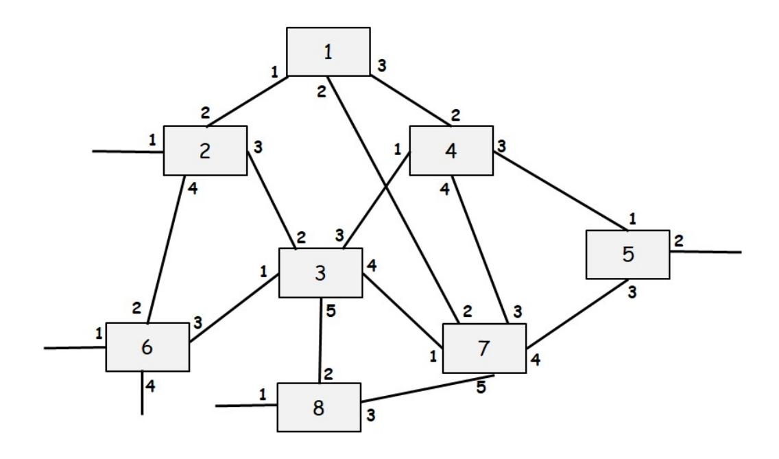
Solution